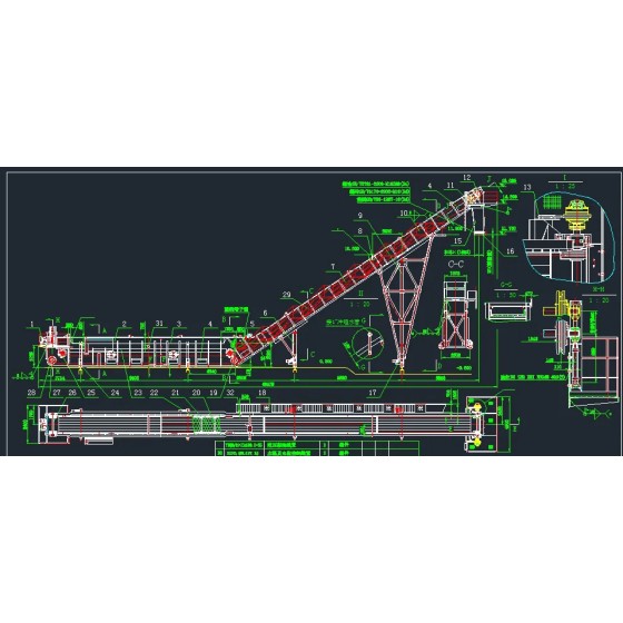
刮板捞渣机液压驱动系统
使 用 维 护 说 明 书
目录
1. 主要技术参数
2. 泵、电机技术参数与设定
3. 液压系统安装使用维护说明
4. 液压元件清单
5. 液压动力站外形尺寸
动力站外形图
液压原理图
端子箱电气接线图
液压管路布置图
液压泵站装配图
主要技术参数
主工作电压: 380V/50Hz
油箱容积: 300L
液位开关:
离油箱顶面的距离: 低液位 250 mm
最低液位 320 mm
温度开关: 最高温度 65℃
警告温度 60℃
冷却器启动温度 50℃
低温报警 20℃
电加热器启动温度 10℃
过滤器:
过滤精度: 5µm
污染物堵塞开关: 2.5bar
旁通阀: 3.5bar
风冷却器:
设计环境温度: 30℃
电机额定电压: 380V/50Hz
电机功率: 0.55KW
电机额定转速: 1450rpm
泵、电机技术参数与设定
泵单元
泵:
型号: PV046R1K1T1NMFC
最大流量(1480rpm): 70L/min
最大压力 : 350 bar
泵压力补偿器压力: 200bar
压差: 30bar
P油口压力传感器: 0~400bar
电机:
型号: QA200L4A B35
功率: 30KW
转速: 1480rpm
液压马达
型号: CA210C
额定扭矩: 42000NM
最大扭矩: 63000NM
动力站安装使用维护说明
1. 工作原理
动力站的职能是在适当的时候,为液压马达(或其它液压系统)提供必须的流量和压力,其原理如图,动力站中有一台由电机驱动的液压泵,主泵是用于开式系统的轴向柱塞变量泵,主泵出来的油经过电液比例换向阀进入液压马达,推动马达运转。系统中经过电液比例换向阀的前后的压力差被引入液压变量泵变量控制机构,系统输出流量根据压差的大小来自动调节。当增大电液比例换向阀的开口时,两端压差变小,为保持两端压力差不变,通过的流量就要增大,变量泵输出的流量就增加,反之,则流量减少。液压泵自身带最高压力限定,当系统压力超过设定的最高压力时,液压泵排量会自动为零,没有液压油输出。从液压马达输出的液压油经阀块和回油过滤器、风冷却机流回油箱。马达泄漏油通过泄漏油回路和泄漏油过滤器回油箱。在泄漏油回路上有一快速接头,用于向系统加油。
液压系统设有油温和油位警告、报警信号,当油温超过60℃、油位低于设定低油位时,油温计和液位计会动作,发出警告信号。当油温超过65℃,或油位低于设定的最低液位时,油温计和液位计又会动作,发出报警信号。当油温超过设定的风冷却器启动温度时,风冷却器会自动打开。
2. 液压系统部分元件说明
2.1 柱塞变量泵PV046R1K1T1NMFC,详见有关泵的样本
2.2 电机 ABB QA200L4A 30KW 380V 50Hz IP55 B35
2.3 温度开关上内部表盘的位置
动作
温度标准
内部表盘的标准位置
报警信号,需停车
达到65℃以上,需停车
1
警告信号
达到60℃以上发出警告
2冷却器开始工作
超过50℃启动冷却器
3低温报警
低于20℃以上发出警告
4电加热器开始工作
低于10℃启动电加热器
52.4 压力表上的隔离阀
当不用压力表时,拧紧隔离阀。如果压力表连续处于压力作用之下,将可能会损坏。
2.5 液位开关
液位开关的层次
液位
相关动作
液面距油箱顶部距离 mm(in)
低
警告
250(9.84)
最低
报警,同时动力站停车
320(12.6)
3. 液压油
3.1液压油的选择
该动力站设计为主要使用在传统石油基础上提炼出来的液压油。液压油的选择可以向油液供应商查询。但是,所使用的液压油必须满足以下要求:
¾ 满足IP334(DIN51354)所述的FZG90测试第11段的要求。
¾ 含有抗氧化剂以避免氧化、锈蚀和起泡。
¾ 无论是动力站还是液压马达在工作时,液压油在规定时间间隔内,油液粘度在允许范围内。(可以在马达回路上进行测量)
¾ 含水量不超过0.1%,同时对于在工业应用中对设备寿命有较高要求的场合,含水量不超过0.05%。
粘度限制
粘度指标VI
推荐
100
用于有很大临时差别的工作场合
150
粘度 n
最小连续工作
40cSt/187SSU
最小间歇工作
20cSt/98SSU
最大连续工作
150cSt/720SSU
最大间歇工作
1600cSt/7400SSU
在工作温度下,推荐粘度为40~150 cSt(187~~720 SSU)
冷起动时,在低压、低流量下运行,最大允许粘度为1600 cSt。
在本系统中,选用液压油为N100#抗磨液压油。
液压油的清洁度要求
该动力站的泄油和回油管路上装有过滤器。为了达到规定的使用寿命,应遵循下列建议,保持油液的清洁度和定期保养是非常重要的。
清洁度建议
¾ 系统起动前必须进行冲洗,详见“起动前的冲洗”。
¾ 当向油箱中加注液压油时,通过特定的注油连接口加油是很重要的,详见“向系统中加注液压油”。
¾ 系统中的固体颗粒度应该不超过ISO/DIS 4406 16/13(NAS 1638,等级7)。
¾ 含水量应该不超过0.1%,同时对于在工业应用中对设备寿命有较高要求的场合,含水量不超过0.05%。
¾ 使用由PARKER公司提供或推荐的滤芯。
¾ 根据规定的保养周期,对液压油液进行定期分析(见“保养图表”一章)。尤其要警惕的是,在卸下元件进行修复或保养时,万万不可让污物进入液压系统,打开之前首先做清洁工作。
4. 动力站的放置
动力站四周应留有一定的空间,以确保自由通风和有足够的维护空间。所有的管子(无论是水管还是液压管路)在安装时必须留有足够的空间,以便维护。大型的维护(例如:电机或液压泵的更换等)将需要更大的空间。
另外要注意以下各点:
¾ 地基要牢固。(避免振动)
¾ 易于保养与维修。
¾ 妥善保护以避免气候、水雾、重度污染和辐射。
¾ 确保空气流通顺畅,使得电机和风冷冷却器能够很好地工作。
¾ 使管网尽可能地短。
管路中分散的管子最好用管夹夹紧,并固定在一个牢固的地基上,以避免振动。主管路连接一定配用软管。如果风冷冷却器安装在动力站之外的其它地方,必须要考虑到安全,冷却器有锋利的刃口,并且将会在无人注意的情况下起动。
5. 液压连接
在液压连接安装时,必须牢记以下要点:
¾ 连接保护装置须保留到最终装配时再取下。
¾ 非常重要的是,所有管路在安装时必须给予足够的空间,以方便动力站的维修保养。
¾ 液压泵与管路之间一定要用软管连接。
安装前,先用肉眼检查连接的密封面,面上必须没有划痕或裂纹。接头体的搬运要很小心,如果不慎掉在地上,则要检查是否出现划痕,密封是否离位,用液压油测试是否产生渗漏来判断是否有裂纹。接头上的包装必须等到最终安装时方可去除。
a. 法兰连接:
法兰上的螺栓必须交叉拧紧。
b. Jic接头(SAE J514,ISO8434):
拧紧1/4~1/2圈即可,不要过度拧紧接头。
使用尺寸正确的工具,否则接头可能会损坏或难以拆卸。
注意:所有的接头都可能受热膨胀或受到振动而松动,此时需要再次拧紧
接头。
c. 管夹
通常管夹之间的距离如下:
D£25mm(1 in),1500~2000mm(59~79 in)。
D³25mm(1 in),2000~2500mm(79~98 in)。
钢管在弯曲的前段与后段以及过渡到软管时,都必须用管夹夹紧。
6. 电气连接
a. 接线盒
根据附带的技术文件上的接线图,将电线连接到接线盒内的接线端口。
b. 风冷冷却器
铭牌上标注有电压及连接方式,将电机与电源相连。检查风扇的旋向,在冷却器上标有气流箭头所示方向。标准为抽风形式。
c. 主电机
根据铭牌上的数值进行主要的电压连接。
7.起动前的冲洗
在动力站的主油管上接上一个压力过滤器和一个单向阀,过滤器应连接到液压泵的回油管一侧。过滤器的过滤精度为 b10=75 或者更高。冲洗过滤器的大小应该与液压泵的相关流量相匹配,通过过滤器的压力与流量不应超过过滤器所允许的最大压力与流量。主油路与马达连接的两端管接头油口用软管连接,组成一个回路,使得整个系统都可以被冲洗。要小心确保从液压泵出来的油液沿着单向阀方向流动。
装机功率较小的动力站,应该用最大流量冲洗至少2个小时。装机功率较大的动力站,冲洗时间应该相应延长。
8. 起动步骤
8.1 起动之前
清洁度要求
¾ 必须对液压系统彻底冲洗,确保系统内部绝对清洁。
¾ 在加注液压油之前再检查系统的清洁度。
管路系统检查
¾ 连接部位是否已经拧紧?
¾ 管路系统是否已经清洁?
¾ 安装后的管路系统中是否有应力存在?
¾ 所有的管路是否根据安装图或布管图布置?
电控部件检查
¾ 检查电机、控制系统与其它的电气元件的电压是否正确。
¾ 手动检查电气元件与监测系统的功能。对不能正确作动的元件要检查接线是否正确,是否可能人工操作。向油箱中注油时,检查液位开关与液位计。
8.2 向系统加注液压油
加油之前
¾ 检查所用的液压油的牌号与质量。不要将不同牌号的液压油混合使用。
¾ 检查装液压油的容器、油箱与软管不要受水或其它物质的污染。
¾ 当第一次加油时,用堵头堵上液压马达上的泄油口Dx,以免未经过滤的液压油进入马达壳体中。
加油
要用带过滤器的加油车向液压系统加油,滤芯过滤精度为10m或者更高。未经过滤的新油也会将污物带入液压系统中,因此一定要通过过滤器,绝对不能通过空气滤清器向油箱中加油。
用加油车加油时,一定要使用特殊的快速接头。这种快速接头经完全防锈处理,并且连接非常方便。第一次加油时,用肉眼观察液位计,油箱中的油液必须达到最大液位以下20mm的地方。向油箱中加油时,也可顺便检查液位开关与液位计的功能。
8.3 初始起动程序
注意!
¾ 确保驱动系统和被驱动机构处于运行待命状态,警告相关区域内的所有工作人员起动即将开始。
¾ 不要用有缺陷的工具或控制元件操作动力站。
¾ 易燃物品需远离动力站。
¾ 在起动期间,液压系统内嵌入的污物颗粒将被冲洗出来,因此在整个起动过程中要一直观察过滤器指示器。在冷天起动时,过滤器可能显示旁路。运行一段时间后,按下可视指示器就可。如果系统已经达到工作温度而指示器显示不能消除,则必须更换滤芯。
第一步 起动之前
¾ 检查油箱中的液位,并再次加油使油箱中的液位达到最大液位以下20mm的地方。
¾ 检查是否有一些液压元件需要添加干净的液压油,例如:
*通过油泵的泄漏口往油泵的壳体内加入干净的液压油,直至气体完全排光,液压油溢出;
*通过液压马达的泄漏口往液压马达的壳体内加入干净的液压油,直至高位泄油口液压油溢出;
¾ 检查安全设备。
¾ 确保所有阀件的吸油口、压力油口和液压泵的进油口一侧以及泄油管路上的一些阀件都处于开启状态。
¾ 检查冷却器是否开启。
第二步 液压泵短时间无负载起动
首先要检查液压泵的转向是否正确,不正确的转向会引起液压泵的损坏。电机上有清楚正确的转向标志。动力站需首先在完全无负载的情况下起动动电机。
第三步 较长时间液压泵无负载运行
液压泵在无负载状态下运行较长的一段时间,直到系统已经稳定,并且可控制操作。
¾ 检查油箱中的液位,由于需油液来充满液压系统中的部件,此时需要再次加液压油,使油位恢复到原来的状态。
¾ 检查不正常的噪音或振动。
¾ 根据附带的技术文件中的液压系统图中所标明的数值,检查动力站中一些指定的压力值。这些压力值在工厂中已经被预先调定通常不需调节。
¾ 检查泄漏点。
停下电机
¾ 纠正以上各点中发现的所有缺陷。
¾ 检查所有的连接、螺栓等等,如果必要重新拧紧。
¾ 完成后重新起动。
第四步 对液压系统加载
当液压系统在无负载状态下的功能已经达到令人满意的程度时,就可以对液压系统进行加载了。
¾ 逐渐增加负载,直到获得满意的操作。
¾ 在此过程中,可能必须对流量、斜盘倾角等进行一些调整。
¾ 使系统循环往复工作,直到系统达到正常的工作温度。
第五步 检查
¾ 检查不正常的噪音或振动。
¾ 检查安全设备的功能。
¾ 检查油箱冷却器控制是否稳定。
¾ 检查泄漏点。
¾ 检查液压泵的补偿压力控制是否设定为适当的数值。出厂前,这些设定值已经根据用户的要求被预先调定,通常不需调节。
¾ 必须检查工作压力,确保其符合要求。
第六步 停下电机
¾ 纠正以上各点中发现的所有缺陷。
¾ 检查过滤器指示器。由于过滤器会不断过滤液压系统中的污物颗粒,所以系统运行中更换滤芯是正常的。更换滤芯时,要小心,以免将污物带入液压系统。
¾ 检查所有的连接、螺栓等等,如果必要重新拧紧。整理动力站内部和周围。保持整洁干净。
9. 保养
有计划地对液压系统进行保养,可以防止液压系统的失效,同时使系统能按规定有效运行。这种特定的保养程序将取决于设备的特性、设备工作的环境与工作周期以及系统对生产的重要程度。为了经济地优化保养周期,建议作寿命周期费用(LCC)分析。
日常检查,投入运行后第一周
¾ 油液泄漏
¾ 油箱中的液位
¾ 工作温度
¾ 系统压力
¾ 系统性能与总体状况
¾ 不正常的噪音
¾ 过滤器的污染指示器
每次起动前的检查
¾ 油液泄漏
¾ 油箱中的液位
¾ 吸油阀是否打开?
¾ 过滤器的污染指示器
经常检查
¾ 不正常的振动
¾ 不正常的噪音
¾ 油液泄漏
¾ 油箱中的液位
¾ 动力站是否比较干净?气流通道是否畅通?
¾ 通常的压力值是否稳定?
¾ 通常的作动器是否平稳?
¾ 工作温度
¾ 驱动系统是否运行平稳?
¾ 过滤器的污染指示器
预定的保养
在特定周期内有计划地保养,包括下列检查和行动:
¾ 经常检查中的所有各点
¾ 检查所有的压力值
¾ 检查系统周围固定的温度值
¾ 从动力站排放阀放出水和泥浆
¾ 检查电机
¾ 检查监测设备 / 开关等元件的功能
¾ 清洁有污物的区域
¾ 检查电线
¾ 检查泄油管流量和泄油管油液状况
¾ 检查软管、连接和液压泵,注意是否有裂纹、泄漏等清况发生
¾ 通过检查孔检查安全联轴节。
用于检查或替换的绝对最大周期
蓄能器
空气滤网
油液过滤器
油箱上的空气滤清器
液压油
第一次工作100小时之后
3个月或工作500小时之后
检查O型密封圈和止推环是否损坏,如果必要,更换该部件。
3. 安装过滤器盖头。用手拧紧到拧不动,再后退1/8圈。
11. 液压油的检查
我们推荐液压油每6个月要化验一次。这种化验包括粘度,氧化程度,含水量,杂质和污物含量。在绝大多数清况下,你的油液供应商都可以从事化验工作,提供液压油目前状况的说明,并推荐采取适当的措施。如果化验标明该液压油的品质不能满足“液压油的清洁度要求”的要求时,就不能再投入使用,必须马上进行更换或清洁。
12. 电机的润滑
润滑30 kW以上的电机
1. 清洁润滑脂注入口。
2. 用润滑脂润滑电机,使用注脂枪加注。
润滑脂
当重新加注润滑脂时,必须使用符合下列性质的特殊球轴承润滑脂。
¾ 使用优质锂基或合成锂润滑脂
¾ 在40℃时,基本粘度为110~140cSt。
¾ 符合NLGL标准2级或3级
¾ 温度范围为-30℃~+120℃,连续。
许多润滑脂制造商都能提供高品质的润滑脂。如果润滑脂的型号发生变化,再次添加的润滑脂难以与先前的保持一致时,要在短期内多加注几次,以取代旧的润滑脂。
电机的通风口
检查电机上的通风口是否被脏物堵塞,空气是否很容易进入电机。
13. 空气滤清器的更换
1. 清洁空气滤清器周围的表面。
2. 拧下盖帽并更换滤芯,
3. 装上盖帽,确保没有外来物质进入油箱。
14. 风冷冷却器的清洁
风叶的清洁
¾ 清洁风叶最容易的方法是使用压缩空气或用水清洗。
¾ 可以使用脱脂剂和一个高压冲洗系统处理污垢。当使用高压冲洗系统时,小心使喷头与风叶平行。
清洁油液冷却管的内部
将冷却器与闭环回路相连,使用高氯化物冲洗冷却管内部。在将冷却器重新连接到液压系统之前,应该再用液压油冲洗一次。
15. 正确的维修
在卸下液压或电气元件之前,首先断开与动力站的连接。确保系统与电机处没有危险存在。
拆卸之前
¾ 对动力站进行故障诊断和进行适当的测试。
¾ 清洁所有的装配件和元件,牢记相关的警告,以免脏物进入系统。
¾ 拆卸工作仅能由专业维修人员来做。
拆卸
¾ 标志所有的部件,并保护精加工面或机械表面。
¾ 拆卸时检查所有的部件是否磨损或损坏。
¾ 如果液压油需放出,要再次投入使用时,接油的容器必须是干净的,同时不用时要用盖子封住。
¾ 重新组装之前,使用合适的溶剂清洁所有的金属部件,然后放置在一块干净的麻布上吸去油液。
重新组装
¾ 用系统液压油润滑
¾ 用新的相同规格的备件替换所有的密封、垫片和O型密封圈。
¾ 确保管路连接完全密封
¾ 按照加注液压油的要求,重新向系统中加油。
16. 故障排除
故障
可能原因
处理方法
动力站不能起动
电机的主电压为零
相关商品
标签 除渣机设备, 捞渣机图片, 捞渣机张紧轮, 水电站自动捞渣机, 捞渣机原理, 捞渣机液压系统原理, 捞渣机张紧装置工作原理, 捞渣机生产厂家, 除渣机, 锅炉捞渣机的作用, 液压比例阀工作原理, 液压关断门原理图, 扒渣机液压管路连接图, 液压泵站工作原理图, 捞渣机生产厂家 捞渣机液压原理图, 捞渣机液压系统原理, 捞渣机液压马达内漏现象, 捞渣机张紧装置, 捞渣机原理


